

 0
 0
Engineers who write a comprehensive English B2B educational article about aluminum die casting for the US industrial market. Target mechanical engineers who fix most cost and quality decisions at the CAD stage. Geometry changes after tooling is cut carry steep penalties. A small set of rules governs clean fill, reliable ejection, and stable tolerance. Teams that write a comprehensive English B2B educational article about aluminum die casting for the US industrial market. Target mechanical engineers who apply these rules early avoid defects. Designers who write a comprehensive English B2B educational article about aluminum die casting for the US industrial market. Target mechanical engineers who settle material and geometry choices before release protect project budgets.
Key Takeaways
- Keep wall thickness uniform to prevent defects like porosity and warping.
- Add draft angles to all walls for easy part removal and longer tool life.
- Specify tight tolerances only where function requires them to control costs.
Wall Thickness
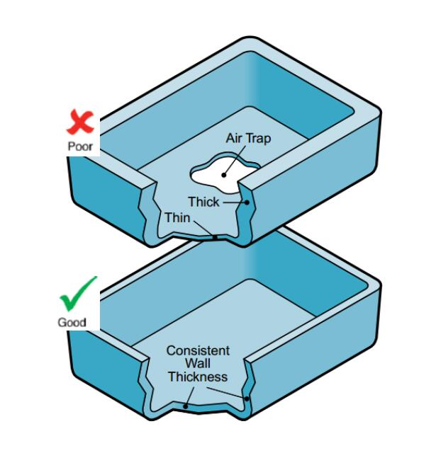
Wall thickness is the single most influential geometry decision in aluminum die casting. It governs how molten metal fills the cavity, how the part solidifies, how it ejects, and how much material the finished component consumes. Engineers who control wall thickness at the CAD stage prevent the majority of casting defects before a single tool is cut.
Keep Walls Uniform
Uniform wall thickness is the foundation of a sound die casting design. When every section of the part cools at a similar rate, the metal solidifies evenly and internal stress stays low. A designer who maintains consistent walls gives the process a predictable thermal profile, and the result is a part that holds tolerance and resists distortion.
Non-uniform walls break that balance. Thick sections hold heat longer than thin ones. The thin area freezes first, and the still-molten thick area cannot draw enough liquid metal to compensate for shrinkage. Internal voids form, and the part carries hidden weaknesses that may only surface in service. A common misconception holds that thicker walls are stronger. In practice, an over-thick boss or pad cools slowly and can be full of porosity, so local strength drops rather than rises.
Thickness variation also drives a chain of related defects. Uneven cooling produces warping and dimensional error. Abrupt changes in section create stress hotspots that are prone to cracking. A thick-to-thin step can slow the metal front and cause cold shuts, where two flow fronts meet but fail to fuse. Thin areas that freeze too early may cause misruns, leaving the cavity incompletely filled. Each of these defects adds cost through scrap, sorting, and leak-test stoppages, and each one traces back to a wall thickness decision made on the drawing.
The practical rule is simple. Keep the main wall as uniform as function allows, and treat every intentional thickness change as a feature that needs justification and careful geometry.
Recommended Thickness Ranges
Industry guidance converges on a workable band for aluminum die casting. Dynacast cites approximately 2 mm as a typical wall thickness for the process. NADCA gives a typical range of 0.040 in to 0.200 in (about 1.016 mm to 5.08 mm), with 0.020 in (0.50 mm) achievable for small castings after consultation and optimization. General design guidance places the recommended band between 0.5 mm and 5 mm (approximately 0.02 in to 0.2 in), depending on alloy, part configuration, size, and application.
The table below summarizes typical values by casting size. These figures serve as a starting point for design review, not as fixed limits. The die caster should confirm final values against the specific alloy, flow path, and tooling plan.
| Category | Recommended Wall Thickness |
|---|---|
| Typical design range | 2.0 mm to 3.5 mm |
| Wider acceptable range | 1.0 mm to 5.0 mm |
| Minimum – small casting | ≈0.5 mm (0.02 in) |
| Minimum – medium casting | ≈1 mm (0.04 in) |
| Minimum – large casting | ≈2 mm (0.08 in) |
| Maximum – small casting | ≈5 mm (0.2 in) |
| Maximum – medium casting | ≈10 mm (0.4 in) |
| Maximum – large casting | ≈15 mm (0.6 in) |
Two principles sit behind these numbers. First, thinner walls save material and shorten cycle time, which lowers unit cost. Second, walls below roughly 0.5 mm raise the risk of cold shuts and misruns because the metal freezes before the cavity fills. Maximum wall thickness should ideally stay under 5–6 mm unless the design includes proper coring, cooling, feeding, and validation. A heavy section without those provisions becomes a porosity trap and a thermal imbalance that shortens die life through heat checking.
Transitioning Between Thicknesses
Some parts genuinely need a change in section, such as a reinforced mounting pad or a thicker sealing surface. The goal is to make that change gradual. An abrupt step alters metal velocity and creates a thermal discontinuity. The thin side may freeze before the cavity fills, while the thick side stays hot and shrinks later. Progressive transitions, including tapers, blended radii, cored pockets, and ribbed transitions, keep the flow smooth and the solidification sequence under control.
A widely used rule sets the transition length at no less than three times the change in thickness. A wall that moves from 2 mm to 4 mm, for example, needs a taper of at least 6 mm. Where a transition is unavoidable, a gradual taper at a 1:4 ratio provides a safe target. Designers should avoid section changes that exceed 2:1 without a transition.
Coring out heavy sections is often the better answer than tapering them. Hollowing a thick boss or pad from the back leaves a uniform wall and removes the mass that creates hot spots. Ribs and gussets add stiffness to thin walls without thickening the whole section, and a rib thickness of roughly 50–70% of the attached main wall prevents the rib from forming its own hot spot. Generous radii at rib-to-wall junctions reduce stress concentration at the same time.
Fillet values deserve feature-by-feature attention rather than one global number. The rib root, a machined pad, and an internal corner each carry different risk, and the design review should state the proposed radius and its reason at every high-risk junction. Geometry also has to work with gating, venting, and cooling. Metal should reach the critical thin path first, overflows and vents should sit at the final flow fronts, and no single heavy pad should control the cycle. Simulation predictions confirmed by trial castings close the loop before production begins.
Draft Angles
Draft is the taper built into every side wall and core of a die cast tool. It allows the solidified part to leave the mold cleanly. Designers who specify draft at the CAD stage prevent ejection damage and protect tool life.
Why Draft Is Required
A cooled aluminum part must come out of a recessed mold. Walls at 90° with no draft create full contact between part and steel. The part sticks, and ejection becomes much harder. A stuck part is very likely to suffer damage during forced removal. A slight taper along the walls provides clearance at the top of the die and allows easy removal. Aluminum is a notably stubborn metal, so draft matters even more here. The sequence below shows the failure chain:
- The solid part must leave the recessed mold.
- Vertical walls with no draft cause sticking.
- Forced ejection damages the part.
- A slight taper provides clearance and easy release.
Typical Draft Values
A 2° draft angle is a common starting point for aluminum die casting. This baseline overcomes friction and shrinkage forces without noticeably changing part geometry. Engineers then tune the angle per feature.
| Feature | Standard Draft | True Factory Minimum |
|---|---|---|
| Outside cavity walls | 1.0° | 0.5° (mirror-polished steel) |
| Inside core elements | 2.0° | 1.5° (prevents shrink grip) |
| Deep pocket ribs | 3.0° | 2.0° (with blend radii) |
Textured surfaces need 3–5° or more because micro-undercuts resist ejection.
Inside vs. Outside Walls
Inside and outside walls behave differently during cooling. The casting contracts away from the cavity, so outer walls need less draft. The casting contracts onto the core and grips it, so inner walls need more.
| Wall Type | Recommended Draft | Reason |
|---|---|---|
| Outer walls (cavity) | 1–2° | Part shrinks away from cavity |
| Inner walls (cores) | 2–3° | Part shrinks onto core and grips |
Deep ribs and bosses call for 3° or more. Non-critical internal walls may sometimes drop to 1°.
Fillets and Radii
A fillet is a rounded transition between two surfaces, called out on a drawing as a radius such as R1.0. Fillets and radii serve as smooth transitions in die casting designs. They prevent stress concentrations and improve durability, strength, and visual appeal.
Reducing Stress Concentration
Sharp corners act as natural stress concentrators. Cracks often initiate where stress peaks under load, vibration, or thermal cycling. A fillet spreads that stress over a larger area instead of focusing it at a point. The curved shape lets stress flow gradually, and the radius directly controls the stress concentration factor (Kt). A larger radius gives a lower Kt and thus lower peak stress. Stress flow lines curve gently around a fillet, staying evenly spaced and producing a lower, more distributed stress field. Chamfers make sharper turns at the start and end of the angled flat, which forces stress lines closer together. Because chamfers lack an inherent radius parameter, they reduce stress less effectively than fillets. In highly loaded or cyclically stressed designs, maximizing the fillet radius in critical areas is a key strategy for structural integrity.
Improving Metal Flow
Rounded edges let the molten metal flow smoothly as it moves through the cavity. Sharp corners introduce instability into the metal flow, which can weaken the cast component. Radii also eliminate the need to trim sharp edges and corners in secondary processing. Generous fillets where a boss connects to other cast features further promote a smooth flow of molten metal. For A380 and ADC12 castings, sharp intersections create less favorable flow and concentrate heat during solidification. Fillets support more uniform filling and reduce process sensitivity.
Sizing Fillets Correctly
The appropriate fillet size and shape depend on the specific application. In practice, fillets and radii are typically less than one millimeter. Incorrectly sized fillets and radii can reduce component strength, so each value deserves review against the local load and flow path. Designers should state the proposed radius and its reason at every high-risk junction.
Ribs and Bosses
Ribs and bosses add stiffness and mounting points to a die casting. They also create thick intersections that cool slowly. Designers who size these features correctly prevent sink marks and porosity.
Rib Design Rules
A rib should stay thinner than the wall it supports. Industry practice sets rib thickness at 0.6 × wall thickness, with 0.8 × as the upper limit. A 3.0 mm wall therefore takes a 1.8 mm rib. Rib height should not exceed roughly 5 × rib thickness, and spacing should run 3–5 × wall thickness, or 9–15 mm for a 3 mm wall. A fillet of 0.5 × rib thickness at the base reduces stress and improves flow. Draft of 1–3° per side aids ejection.
Ribs can add stiffness without adding heavy mass, but rib roots and bosses must avoid thick hot spots.
Boss Placement and Wall Connections
An isolated tall boss behaves like a cantilever. Designers should tie it to a nearby wall with directional ribs. Rib orientation should follow the actual load path, whether axial, radial, or overturning. Coring the boss or adding a cast pilot removes thermal mass. Draft belongs on both inner and outer boss surfaces, and the base should blend into ribs and wall. Boss-hole direction also matters for tooling: a hole in the main pull may use a fixed core, while a lateral hole may need a slide.
Avoiding Sink and Shrinkage
A rib as thick as its wall makes the intersection effectively twice as thick. That node cools at roughly one-quarter the rate and almost guarantees a sink mark on the opposite surface. A hollow boss with 2.5 mm walls and a Ø15 mm core keeps cooling uniform. Internal cross-ribs at about 40% of base wall add strength without surface defects.
Tolerances and Surface Finish
Tolerance and finish callouts translate directly into tooling investment, process control, and piece price. A drawing that specifies every dimension to the tightest achievable limit forces extra machining passes, slower cycles, and heavier inspection. A drawing that reserves tight tolerances for functional interfaces keeps cost in check without sacrificing performance. Engineers who understand the standard capability of the process make better callout decisions at the CAD stage.
Standard vs. Tight Tolerances
Standard tolerances represent what a well-controlled aluminum die casting process delivers without special measures. These values cover most functional features and form the baseline for quoting and design review.
| Feature | Typical Tolerance | Notes |
|---|---|---|
| Small features (<25 mm) | ±0.05 mm | Suitable for precise details and small components |
| Medium features (25–75 mm) | ±0.10 mm | Common for housing parts and medium shapes |
| Large features (>75 mm) | ±0.20 mm | More variation allowed as part size increases |
| Hole diameter | ±0.075 mm | Often requires secondary machining for tight fits |
| Hole position | ±0.15 mm | May vary more if far from injection point |
| Flatness (per 100 mm) | ±0.10 mm | Thinner or wider parts may warp during cooling |
| Wall thickness | ±10% of nominal | Example: 2 mm wall = 1.8 mm to 2.2 mm |
Industry standards organize these values into classes. NADCA 2015 defines three classes for North American work: precision, intermediate, and commercial. Precision holds roughly ±0.05 mm on a 25 mm feature. Intermediate sits near ±0.13 mm on the same feature. Commercial allows about ±0.25 mm. ISO 8062-3 uses Dimensional Casting Tolerance Grades instead. DCTG 5 represents a very tight grade for small parts or machined surfaces. DCTG 9 suits general-purpose parts. Higher grade numbers indicate looser tolerances, so DCTG 11 is looser than DCTG 6.
As-cast linear tolerance on a long dimension runs looser than these feature-level figures suggest. Per NADCA Publication 402 and ISO 8062, a 100 mm dimension typically holds ±0.22 to ±0.44 mm as-cast. That range is significantly looser than machined tolerance. Features that need tight tolerance should therefore be machined after casting rather than specified as-cast.
Tight tolerances go beyond standard capability. A precision callout demands more accurate die construction, tighter process control, and often secondary machining. The table below contrasts the two levels.
| Tolerance Category | Typical Value / Description |
|---|---|
| Standard NADCA linear tolerance (aluminum) | ±0.002 in/in (±0.05 mm/25 mm) |
| Minimum limit for small features | ±0.005 in (±0.13 mm) |
| Precision tolerance | Tighter than standard; needs more accurate die construction, better process control, and sometimes secondary machining; raises cost but reduces downstream fitting and assembly issues |
Tight tolerances serve specific industries. Automotive, aerospace, and medical device programs require them wherever safety and performance depend on fit. An engine housing with loose tolerances, for example, could cause vibration or sealing problems. The choice between standard and precision levels rests on part function, required fit, and budget constraints.
Cost Impact of Tight Tolerances
Tighter tolerances do not merely change a number on the drawing. They alter the entire manufacturing process. Achieving tighter callouts requires additional machining passes, more careful workholding, tighter thermal management, and slower, more rigorous inspection. These added process steps directly increase piece price. Tolerance discipline on the drawing is therefore a primary lever for controlling cost.
| Tolerance Level | Effect on Cost Drivers |
|---|---|
| ±0.5 mm (typical) | Baseline inspection, machining, and die complexity |
| ±0.05 mm (tight) | Ramped-up inspection, additional machining, and increased die complexity |
| ±0.2–0.5 mm → ±0.01–0.05 mm (precision) | Increased machining time and QA effort, raising die price and extending lead time |
Designers can offset these cost drivers through several practical measures. They can simplify part geometry, relax non-critical tolerances, consolidate parts, increase wall-thickness uniformity, eliminate undercuts that require slides, and minimize machined features. These measures reduce die complexity, lower secondary machining and scrap, and shorten try-out time. Total part cost typically drops by 10–30% across tooling and per-part spend, depending on baseline complexity.
A disciplined tolerance review pays for itself. Each callout should trace to a functional requirement. Dimensions that only look important on a drawing add cost without adding value. The design review should separate critical interfaces from cosmetic or clearance features and assign tolerance levels accordingly.
As-Cast Surface Finish Expectations
Aluminum die casting delivers a smooth as-cast surface without secondary operations. Die casting, including squeeze casting, can achieve a surface finish as fine as 20 RMS in extreme cases. Material selection affects finish quality as well. Alloys with lower melting points yield smoother surfaces, so aluminum castings generally show a smoother as-cast finish than iron or steel castings. For aluminum die casting, an as-cast finish approaching roughly 20 RMS is achievable in best-case conditions.
Typical production finishes sit somewhat coarser than that extreme. Die surface condition, alloy choice, and process parameters all influence the final result. A polished die cavity transfers its finish to the casting. A die with heat checking or erosion transfers those defects as well. Designers should treat as-cast finish as a process capability to confirm with the die caster rather than a guaranteed value on every surface.
Surface finish callouts follow the same discipline as tolerance callouts. Cosmetic surfaces and sealing faces may justify a tighter specification. Hidden internal surfaces and non-functional areas rarely need one. A finish requirement that exceeds as-cast capability forces polishing, blasting, or machining, and each step adds cost and lead time. The design review should state which surfaces carry a finish requirement and why.
Alloy Selection and Design
Alloy choice constrains geometry, tolerance, and performance. Engineers who lock the alloy early give the tool designer a stable target.
Common Aluminum Alloys
The 380 family dominates general-purpose die casting. Each grade offers a distinct balance of properties:
- Alloy 380 — a cost-effective standard balancing strength, corrosion resistance, and thermal conductivity; suited to housings, brackets, and frames.
- Alloy 383 — better fluidity and heat resistance than 380; ideal for thin-walled, complex parts.
- Alloy A360 — superior corrosion resistance and higher strength than 380; chosen for higher-stress parts and outdoor service.
- Alloy 413 — exceptional pressure tightness and corrosion resistance; used in hydraulic and sealed components.
- Alloy B390 — exceptional wear resistance and hardness; used in pumps and brake components.
How Alloy Choice Affects Design
Aluminum castings shrink roughly 0.4–0.6% by volume as they cool. Shrinkage helps release from outer die walls but grips internal cores, so draft must compensate. Silicon content drives fluidity and shrinkage behavior, and adjusting it within a spec fine-tunes dimensional stability for tight-tolerance work.
Al-Si die-casting alloys offer excellent fluidity for complex shapes and dominate non-heat-treatable die-casting aluminum, making the Al-Si system a primary target for property optimization.
Matching Alloy to Application
Selection starts with the operating environment, then moves to mechanical properties, corrosion exposure, conductivity, processability, and post-casting needs.
| Application | Recommended Alloy(s) | Key Reason |
|---|---|---|
| Automotive engine and structural parts | A390, A413, A380 | Strength, wear resistance, thermal performance |
| Consumer electronics | A380, A360 | Lightweight, precise, corrosion-resistant |
| Marine and outdoor equipment | A360 | Superior corrosion resistance |
| General industrial components | A380, A383 | Balanced strength, cost, machinability |
| Heat-dissipating parts | A413 | High thermal conductivity |
Cost and availability close the decision. Engineers should weigh alloy price against scrap rates and finishing needs, then confirm the choice with the die caster during design review.
Common Design Mistakes
Most die casting defects trace back to a handful of geometry decisions. Designers who recognize these patterns early avoid expensive tooling changes later.
Sharp Corners and Thick Sections
Sharp corners concentrate stress and invite cracking and fatigue failure. Large, isolated heavy sections cool at a different rate than thin areas, so shrinkage voids and weak spots appear. Both mistakes raise tooling stress and shorten mold life.
| Design Mistake | Why It Is a Problem | Recommended Fix |
|---|---|---|
| Sharp corners and edges | Stress concentrates at sharp corners, making parts prone to cracking and early fatigue failure | Add fillets and radii to distribute stress evenly and extend component life |
| Large, isolated heavy sections | Concentrated masses cool at different rates than thin areas, causing shrinkage voids and structural weakness; also raises tooling stress and shortens mold life | Avoid isolated thick masses; design for more uniform sections |
Uniform wall thickness remains the core rule. Molten metal moving from a thin wall into a thick pocket cools unevenly. The thick region stays liquid longer, then shrinks as it freezes, pulling voids into the metal or sinking the surface. Aluminum walls typically run 1.5–3 mm. When stiffness is needed, a rib network carries load while keeping metal thin and fast to freeze. Each rib should measure about 60% of the wall it joins. Bosses follow the same logic: blend them with fillets and support them with ribs rather than leaving an isolated column of thick metal.
Undercuts and Deep Features
Undercuts cannot form in a standard die casting without retractable slide cores or secondary machining. They increase both the complexity and the cost of the die. Internal features face the same constraint, so designers should avoid undercuts and internal features wherever possible.
Any protruding lip, recessed side cavity, or lateral channel obstructs the straight vertical pull path. The geometry physically locks the solidified part inside the steel cavity. Deep lateral features force toolmakers to add hydraulic side-action sliders that must withstand hundreds of tons of injection pressure. Any slight movement causes heavy metal flash at the seam. Each slider intersection with the main mold wall also leaves a visible parting line that requires aggressive secondary polishing. Moving tracks inflate the initial tooling invoice and introduce failure points. Liquid aluminum seeps into sliding-track gaps and grinds mechanisms to a halt. Designers can often extend lateral holes to the top edge as U-shaped slots or shift features onto the parting line to avoid expensive side-actions.
Ignoring Ejection and Tooling Needs
A design that ignores ejection and tooling needs creates failures that surface only at production. Without draft, the part sticks to the die. Ejection becomes inconsistent, surface damage increases, and tool wear accelerates. Even 1–3° of draft dramatically improves tool life and cycle efficiency. Skipping draft does not save cost; it increases it.
Designing to Avoid Moving Cores: Complex three-dimensional shapes are achieved using moving cores that slide in the die. If a satisfactory effect can be achieved without these moving cores, the die will cost significantly less — extra moving die members add cost that must be justified by feature value or material savings.
Design for Reliable Die Ejection: The ejector pin arrangement must ensure the casting and runner move squarely without distorting the component. An ejector pin must be provided close to every position where the casting tends to grip the tool, positioned so ejector strain loosens the casting from the tool. Casting design can make this job easy, difficult, or impossible. Ejector pins leave marks (typically ~5mm diameter, ±0.4mm), so the component should be designed so these marks do not disfigure visible faces.
Treating tooling as secondary raises tooling cost and maintenance frequency. Simple geometry almost always wins long term.
Write a comprehensive English B2B educational article about aluminum die casting for the US industrial market. Target mechanical engineers who apply uniform walls, adequate draft, generous fillets, and well-placed ribs to prevent defects before they start. Specify tolerances and surface finish only where function requires them. Choose the alloy early. Engage the die caster during design review. Write a comprehensive English B2B educational article about aluminum die casting for the US industrial market. Target mechanical engineers who act early keep cost low and quality high.
FAQ
What is the minimum wall thickness for aluminum die casting?
Most aluminum die castings use walls between 1.0 mm and 5.0 mm. Small parts can reach 0.5 mm after consultation with the die caster. Thinner walls raise the risk of cold shuts and misruns.
Does every die casting design need draft angles?
Yes. Every wall and core needs draft for clean ejection. Outer walls typically take 1–2°, and inner walls take 2–3°. Textured surfaces need 3–5° or more.
Should engineers specify tight tolerances on every dimension?
No. Standard tolerances cover most features at lower cost. Engineers should reserve tight tolerances for functional interfaces. Each callout should trace to a real requirement.
See Also
Avoid Making The Same Mistake With Aluminum Casting Process Selection
https://www.xuxiangtaimetal.com
Qingdao Xuxiangtai Machinery